Every thermal power plant in India operates with a hidden adversary. It has no moving parts, triggers no immediate alarms, and leaves no visible footprint — at least not at first. It is the slow, invisible chemical attack on your control room electronics driven by the corrosive gases generated by coal combustion, flue gas leaks, cooling tower biofouling, and SCR systems.
By the time most plants notice it, the damage is already done.
The Invisible Threat in Your Control Infrastructure
India’s thermal power fleet operates at approximately 240 GW of installed capacity generating around 74% of the country’s electricity in some of the most chemically aggressive environments in any industry.
Coal combustion produces sulfur dioxide (SO₂) in flue gas concentrations of 500 to 3,000 ppm. Even small leaks from duct joints, ESP hoppers, or induced draft fan casings allow SO₂ to migrate into adjacent control buildings.
Once inside, SO₂ combines with ambient humidity to form sulfurous and sulfuric acid films on electronic surfaces. The same process happens with hydrogen sulfide (H₂S) from coal storage and cooling tower biofouling zones.
Add nitrogen oxides (NOx) from combustion, chlorides from coastal marine aerosols or cooling tower biocides, and ammonia from SCR DeNOx systems and you have a multi-gas corrosion environment that standard HVAC simply was not designed to handle.
This is the environment your DCS I/O cards, protection relays, VFD control boards, SCADA servers, and PLC terminal blocks are operating in right now.
What Standard HVAC Cannot Do
This is one of the most commonly misunderstood aspects of control room protection. Most power plants have air-conditioned control rooms. Many assume that air conditioning equals environmental protection.
It does not.
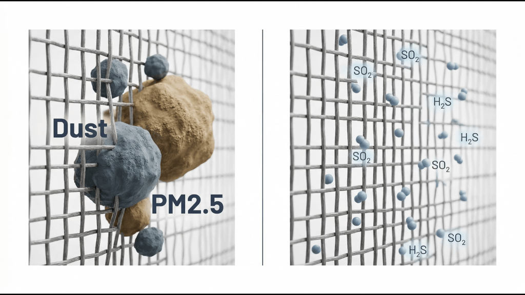
Conventional HVAC filtration even high-quality HEPA systems is designed to capture particulate matter: dust, aerosols, PM2.5. It has no mechanism to remove corrosive gas molecules.
SO₂ at 0.5 ppm, H₂S at 1 ppm, and chlorine at 0.2 ppm pass through standard HVAC filters completely unchanged, continuing into your control enclosures where they react with copper PCB traces, silver relay contacts, aluminium busbars, and terminal block connections.
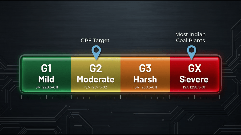
A control room can appear spotlessly clean and still be classified as GX (Severe) under the ISA S71.04-2013 standard for electronic environments, the most aggressive corrosion category, associated with copper corrosion rates exceeding 2,000 Angstroms in 30 days.
According to ISA S71.04-2013, the international governing standard for electronic environment classification, most Indian coal-fired thermal plants without active gas phase filtration measure at G3 (Harsh) to GX (Severe) — well above the G1 to G2 range specified by DCS and PLC manufacturers as the required operating environment for their equipment.
How Corrosion Progresses: The Four-Phase Failure Model
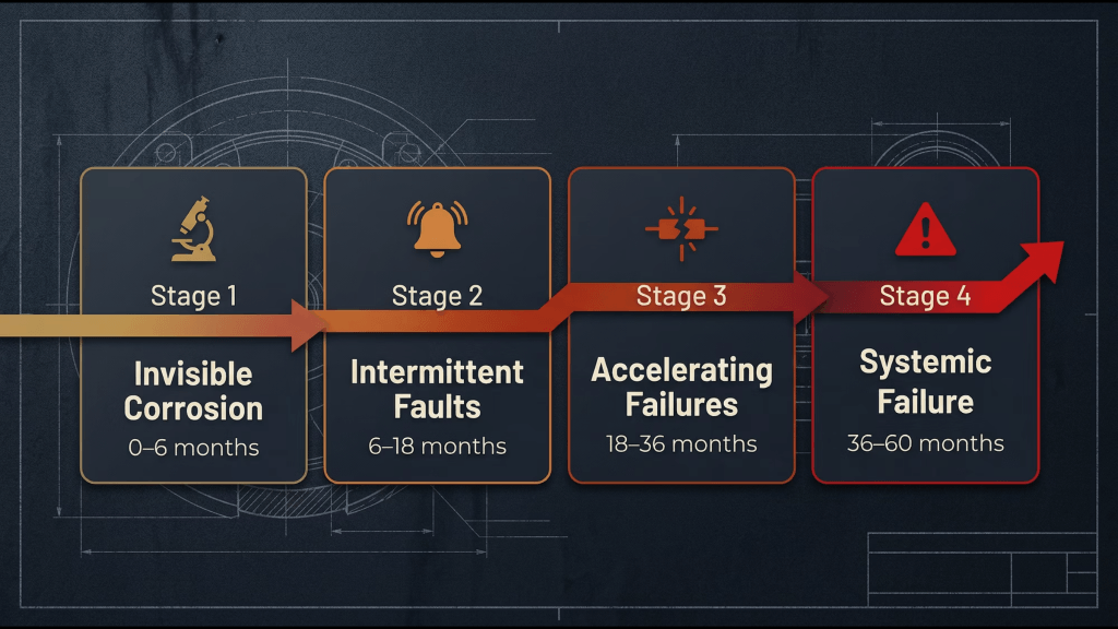
Electronic corrosion in power plant environments does not announce itself. It follows a predictable progression that too often goes unrecognised until the crisis phase:
Phase 1: Invisible Corrosion (0–6 months)
No visible symptoms. Copper PCB traces develop microscopic tarnish. Silver relay contacts begin converting to silver sulfide (Ag₂S) — a non-conductive black film. All systems appear normal. No alarms triggered.
Phase 2: Intermittent Faults (6–18 months)
Nuisance alarms begin appearing: intermittent I/O faults, contact resistance spikes, occasional SCADA disconnects. Operators reset and attribute these to “software glitches.” Maintenance call-outs increase. The pattern is often logged but not yet connected to a root cause.
Phase 3: Accelerating Failures (18–36 months)
Frequent protection relay misoperations. VFD gate driver board failures. Multiple DCS I/O card replacements. PLC CPU degradation. Sensor reading drift becomes persistent. Spare parts consumption grows significantly. Panel replacement cycles begin.
Phase 4: Systemic Failure and Outage (36–60+ months)
Complete DCS controller failure. SCADA blackout. Forced unit outage. Emergency procurement of long-lead DCS components at premium prices. The root cause of corrosion is finally identified. GPF is installed retrospectively at a fraction of what the crisis cost.
The insight that makes this model actionable: the cost of gas phase filtration installed at Phase 1 is typically 1–2% of the cost of a Phase 4 crisis response.
Documented Failure Patterns in Indian Power Plants

This is not theoretical. Power Line Magazine (2018), reporting on DCS upgrade projects across Indian thermal plants, documented that field devices including sensors, actuators, and transmitters were achieving actual service lives of less than 2 to 3 years against a design life of 5 to 10 years.
The root cause: a corrosive micro-environment inside control panels created by SO₂, coal dust, and humidity combining to create GX-severity conditions in ostensibly “clean” control rooms.
The failure signature is consistent: silver-plated relay contacts show brown-to-black Ag₂S tarnish within 3 to 6 months of installation, progressing to complete contact resistance failure within 6 to 18 months, against a design life of 10 to 15 years.
A single protection relay misoperation from this degradation can trip a generating unit. Given the scale of generation capacity involved, even short unplanned outages carry significant operational and financial consequences.
Industry data suggests that 20 to 35% of all forced outages in India’s thermal fleet are attributable to instrumentation, control, and electrical equipment failures, a category in which corrosion is a primary and often overlooked root cause.
The Critical Electronics at Risk
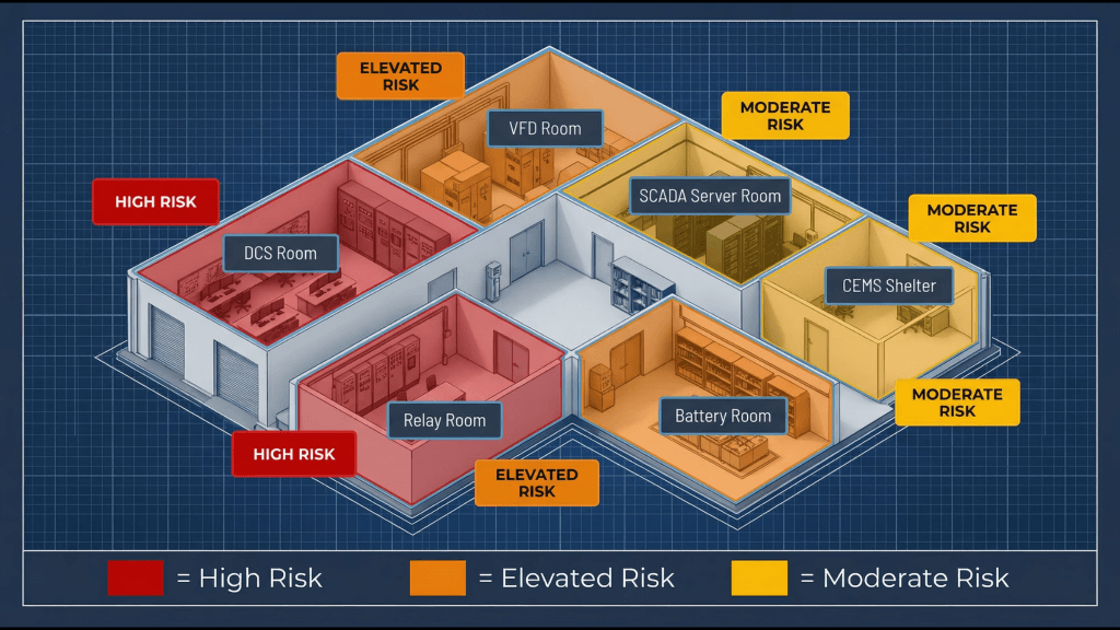
Every zone in a thermal power plant that houses electronics is potentially exposed. The highest-consequence areas include:
DCS Control Rooms and I/O Cards
The central nervous system of plant control. DCS I/O cards, controller processors, and communication modules are vulnerable to copper trace attack and silver contact failure. When DCS control fails, the entire automated process loop for that unit is at risk.
Protection Relay Rooms
Numerical protection relays detect electrical faults and trip circuit breakers within milliseconds. When corrosion increases contact resistance in relay output circuits, the relay either fails to trip allowing catastrophic equipment damage from an uncleared fault or trips spuriously, causing unnecessary unit outages. Both outcomes are operationally severe.
VFD Rooms and Motor Control Rooms
Variable frequency drives controlling boiler feed pumps, induced draft fans, and cooling water pumps are critical to continuous unit operation. IGBT gate driver board corrosion follows the same phase-by-phase progression described above. A VFD failure on key auxiliary equipment can escalate to a full unit shutdown in a short window.
SCADA and HMI Servers
Without SCADA, operators lose real-time visibility into distributed pump stations, cooling water systems, and fuel oil systems. Equipment failures go undetected. Abnormal conditions persist without alarm. In a large multi-unit plant, SCADA failure becomes a compliance and safety risk as much as an operational one.
Battery Rooms and UPS Systems
Lead-acid battery charging releases hydrogen gas and sulfuric acid vapour — both damaging to terminal connections and charger electronics. DC supply failure removes backup power from protection systems and emergency controls at the worst possible moment.
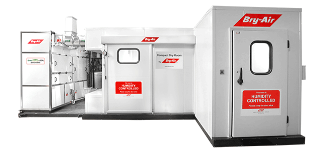
The Gas Phase Filtration Solution
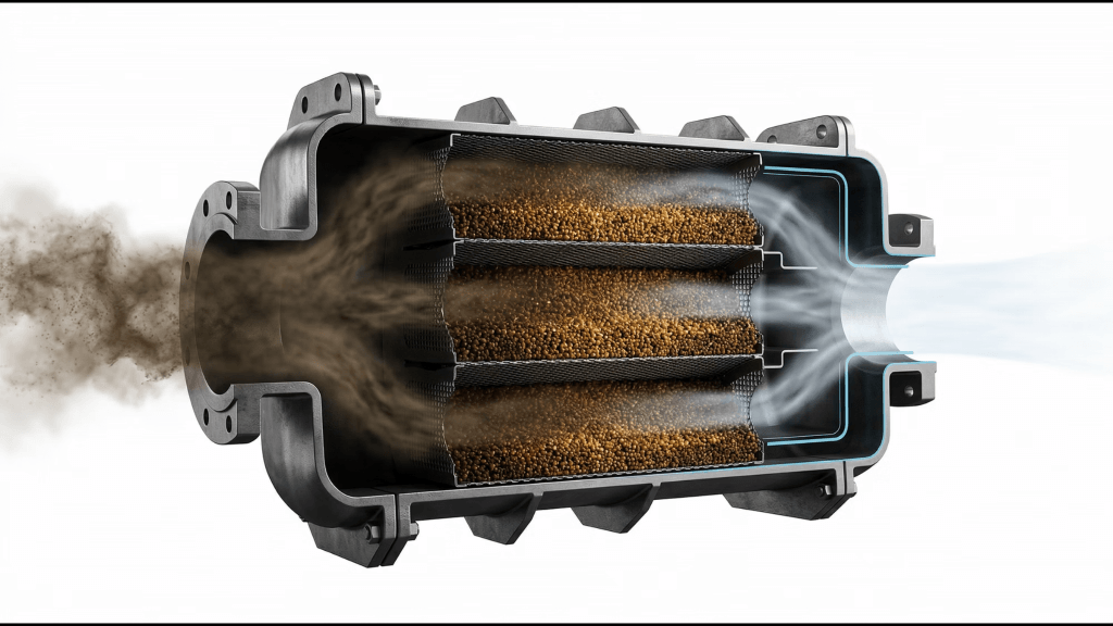
Gas Phase Filtration (GPF) is a molecular-level air purification technology that removes corrosive gases from the air supplied to critical electronic enclosures.
Where conventional HVAC filters capture dust particles measured in microns, GPF employs activated carbon, potassium permanganate-impregnated alumina, and chemically specialised adsorbent media to chemically neutralise reactive gas molecules like SO₂, H₂S, NOx, Cl₂, NH₃, and VOCs, before they reach sensitive electronics.
The result is a measurable, verifiable reduction in atmospheric corrosivity from GX (Severe) toward G2 (Moderate) or better inside protected enclosures the environment that DCS, PLC, and relay manufacturers specify as the required operating condition for their equipment.
GPF does not replace HVAC. It works alongside it, addressing the molecular-level gas contamination that conventional air handling cannot touch.
Where GPF Protects in a Power Plant
A comprehensive GPF deployment is designed to address every critical electronics zone:
- Main Control Room / DCS Room: the highest-consequence zone; SO₂, H₂S, NOx, and chlorides neutralised before reaching DCS controllers and historian servers
- Switchgear and Protection Relay Rooms: relay contacts protected from the 6–18 month unprotected failure window, working toward their 10–15 year design life
- VFD Rooms and Motor Control Rooms: IGBT gate driver boards and capacitors protected from SO₂ and conductive coal dust
- Battery Rooms: H₂SO₄ vapour from lead-acid charging removed; charger electronics and terminal connections protected
- Coal Handling Plant Panels: conductive carbon dust managed through particulate pre-filtration combined with GPF for gas removal
- CEMS Instrument Shelters: protecting the analyser electronics mandated by CPCB for continuous environmental compliance reporting
- Server and Historian Rooms: SO₂ and H₂S removed from air serving IT infrastructure critical to performance records and regulatory data
Why Investment in GPF Makes Operational Sense
Forced outages at thermal power plants carry significant costs in lost generation, restart expenditure, and in some cases regulatory consequence. Industry estimates suggest that a meaningful proportion of those outages trace back to instrumentation and control system failures where corrosion is the underlying cause.
When that root cause goes unaddressed, the consequences compound:
- Control panel and DCS I/O card replacement cycles that should span 10–15 years are compressed to 3–5 years in unprotected GX environments
- Relay replacement frequency runs at multiples of the designed interval, driving up annual C&I maintenance spend
- Spare parts procurement often for long-lead DCS components attracts emergency pricing premiums
- Maintenance teams spend disproportionate time on reactive troubleshooting rather than planned work
Gas phase filtration addresses the root cause rather than its symptoms. The investment is a fraction of the recurring cost of unprotected operation, and it works progressively from the point of installation reducing gas ingress, slowing corrosion, and extending the life of electronics that would otherwise degrade on an accelerating curve.
For O&M teams, this means fewer nuisance trips and a more predictable maintenance schedule.
For plant leadership, it means more stable Plant Load Factor (PLF) performance and reduced outage risk. For finance, it means avoiding premature capital expenditure on electronics that should still have years of useful life remaining.
ISA S71.04 Compliance Standard
ISA S71.04-2013 provides the internationally recognised framework for classifying electronic environments and determining the level of protection required.
Major DCS and PLC manufacturers including ABB, Siemens, Honeywell, and Emerson specify G1 or G2 operating environments in their equipment documentation.
Operation outside these limits voids corrosion-related warranties and creates liability exposure for the plant operator.
ISA corrosivity monitoring through standardised copper and silver exposure coupons, or real-time Atmospheric Corrosivity Monitors (ACM), provides defensible, auditable evidence of environmental conditions relevant in regulatory enquiries, insurance assessments, and vendor warranty discussions.
India’s CPCB mandate for Continuous Emission Monitoring Systems (CEMS) at major power plants creates a specific and practical compliance driver: CEMS analysers are themselves electronic instruments operating in harsh environments. Protecting CEMS electronics with GPF is directly tied to maintaining the uptime these systems must demonstrate.
Start with a Corrosion Risk Assessment

Electronic corrosion develops gradually. In most plants, progression through Phase 1 and Phase 2 happens invisibly, noticed only in retrospect once Phase 3 failures begin escalating maintenance costs and outage risk.
A structured corrosion risk and air quality assessment identifies contaminant levels in critical areas, measures corrosion severity against ISA S71.04 benchmarks, and determines the appropriate GPF configuration for your specific plant layout and gas profile.
Understanding the actual corrosion environment in your control rooms is the first step toward protecting the electronics that keep your plant running.
Frequently Asked Questions
1. Does gas phase filtration work alongside existing HVAC?
Yes. GPF systems are designed as a complementary layer to existing air handling infrastructure. They do not replace HVAC they address the molecular gas contamination that conventional filtration cannot remove.
2. How do we know if our control rooms have a corrosion problem?
ISA S71.04-compliant corrosion classification coupons such as copper and silver exposure coupons deployed for 30 days, provide a baseline measurement and a formal ISA class determination. An Atmospheric Corrosivity Monitor (ACM) provides continuous real-time classification for ongoing monitoring.
3. What gases does GPF remove?
A properly specified system removes SO₂, H₂S, NOx, Cl₂, NH₃, and VOCs. Media blends are selected based on the specific gas challenge at each site a coastal plant requires chloride-targeting base-impregnated carbon; a plant with SCR requires ammonia-specific acid-impregnated carbon alongside the primary media.
4. How long does the filter media last?
Media life typically ranges from 12 to 36 months, depending on inlet gas concentration and system airflow at the specific site. Bry-Air supports ongoing media replacement as part of a lifecycle service contract.
5. Does GPF void existing HVAC or equipment warranties?
No. GPF is additive and it enhances the environment that existing HVAC already conditions. Installing GPF to achieve ISA G1/G2 conditions is actually aligned with what DCS and PLC manufacturers require, and supports rather than conflicts with equipment warranty conditions.